


|
Akcesoria |
|
Akcesoria GSM/LTE |

 |
 |
 |
 |
 |

How to Protect your MikroTik RouterOS??DescriptionTo protect your MikroTik RouterOS?, you should not only change admin's password but also set up packet filtering. All packets with destination to the router are processed against the ip firewall input chain. Note, that the input chain does not affect packets which are being transferred through the router. You can add following rules under /ip firewall rule input (just 'copy and paste' to the router using Terminal Console or configure the relevant arguments in WinBox): /ip firewall rule input add connection-state=invalid action=drop
comment="Drop invalid connections"
/ip firewall rule input add connection-state=established
comment="Allow established connections"
/ip firewall rule input add connection-state=related
comment="Allow related connections"
/ip firewall rule input add protocol=udp comment="Allow UDP"
/ip firewall rule input add protocol=icmp comment="Allow ICMP Ping"
/ip firewall rule input add src-address=10.0.0.0/24
comment="Allow access from our local network. Edit this!"
/ip firewall rule input add src-address=192.168.0.0/24
protocol=tcp dst-port=8080
comment="This is web proxy service for our customers.
Use /ip firewall rule input print packets command to see how many packets have been processed against these rules. Use reset-counters command to reset the counters. Examine the system log file /log print to see the packets which have been dropped. You may need to include additional rules to allow access from certain hosts, etc. Remember that firewall rules are processed in the order they appear on the list. After a rule matches the packet, no more rules are processed for it. After adding new rules, move them up using the move command. How to Protect your MikroTik RouterOS? from being used as Spam Relay?DescriptionTo protect your MikroTik RouterOS? from being used as spam relay you have to:
The web proxy access list is configured under /ip web-proxy access. For example, add following rules to it to allow access from certain hosts (just 'copy and paste' to the router using Terminal Console or configure the relevant arguments in WinBox): /ip web-proxy access
add src-address=192.168.0.0/24
comment="Our customers"
/ip web-proxy access add dst-port=23-25 action=deny
comment="Deny using us as telnet and SMTP relay"
/ip web-proxy access add action=deny
comment="Deny everything else"
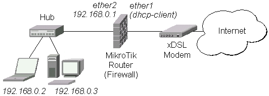
Note, that first you should have rules that allow certain services, and the last rule should always be one that denies access for everything else. Rules are processed in the order they appear on the list. After a rule matches the request, no more rules are processed for it. After adding new rules, move them up using the move command. How to Connect your Home Network to xDSL Line?DescriptionYou have your Home DSL modem installed, and want to have a secure connection to the Internet for your home network. For that, you have to install MikroTik router between the DSL modem and your home network:
Follow the steps below to connect your home network to xDSL line:
How To Keep My Router Up-To-DateDescriptionTo keep your router up to date, you should:
In this How-To section we will show you how to upgrade your RouterBoard's BIOS firmware version.
How to Transparently Bridge two Networks?DescriptionRemote networks can be easily bridged using Ethernet over IP (EoIP) or WDS feature of MikroTik RouterOS?. We will show it for the case when the networks are connected through Atheros wireless interface. Using EoIP, the can be extended to any other type of interfaces, like PPTP, CISCO/Aironet, Prism. WDS works only on Prism and Atheros based cards. Let us assume the following network setup:
Transparent Bridge, using EoIP tunnelFollow the steps below to create transparent bridge using EoIP interfaces:
Test the bridge by pinging from 10.0.0.215 to 10.0.0.216. Note, that the bridge needs 10...30s to learn addresses and start passing through traffic. Similarly you can create transparent bridge if you have prism or CISCO/Aironet interfaces, or encrypted PPTP tunnel. However, the EoIP tunnel can be established between two MikroTik routers only. Transparent Bridge, using WDSYou can also use WDS to bridge 2 networks transparently.
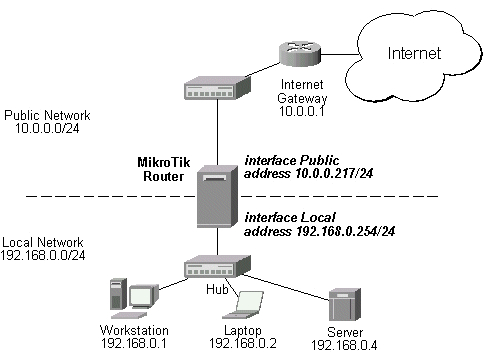
How to Link Public Addresses to the Local Ones?DescriptionThe current topic shows how to configure 'full NAT', i.e. when a computer having it's own address in the local network gets it translated when talking to outer (public) networks.
Let us assume two addresses (10.0.0.216 and 10.0.0.217) are assigned to the router. In this example we will 'full NAT' the internal address 192.168.0.4 to the external 10.0.0.216 one while keeping 10.0.0.217 for the router itself as well as for masquerading the internal network. To add 10.0.0.216/24 and 10.0.0.217/24 addresses to the router's Public interface and 192.168.0.254/24 to the router's Local interface: /ip address
add address=10.0.0.216/24 interface=Public
add address=10.0.0.217/24 interface=Public
add address=192.168.0.254/24 interface=Local
print
Flags: X - disabled, I - invalid, D - dynamic
# ADDRESS NETWORK BROADCAST INTERFACE
0 10.0.0.216/24 10.0.0.0 10.0.0.255 Public
1 10.0.0.217/24 10.0.0.0 10.0.0.255 Public
2 192.168.0.254/24 192.168.0.0 192.168.0.255 Local
While adding the default route to the router you should be aware of having two addresses. You should specify the address that the router will be using while talking to the outer networks: /ip route
add gateway=10.0.0.1 preferred-source=10.0.0.217
print
Flags: X - disabled, I - invalid, D - dynamic, J - rejected,
C - connect, S - static, r - rip, o - ospf, b - bgp
# DST-ADDRESS G GATEWAY DISTANCE INTERFACE
0 S 0.0.0.0/0 r 10.0.0.1 1 Public
1 DC 10.0.0.0/24 r 0.0.0.0 0 Public
2 DC 192.168.0.0/24 r 0.0.0.0 0 Local
Add DST-NAT rule allowing access to the internal server from external networks: /ip firewall dst-nat
add dst-address=10.0.0.216/32 action=nat to-dst-address=192.168.0.4
print
Flags: X - disabled, I - invalid, D - dynamic
0 dst-address=10.0.0.216/32 action=nat to-dst-address=192.168.0.4
To add SRC-NAT rules allowing the internal server to talk to the outer networks having its source address translated to 10.0.0.216, while translating other internal hosts' source addresses to 10.0.0.217: /ip firewall src-nat
add src-address=192.168.0.4/32 action=nat to-src-address=10.0.0.216
add src-address=192.168.0.0/24 action=nat to-src-address=10.0.0.217
print
Flags: X - disabled, I - invalid, D - dynamic
0 src-address=192.168.0.4/32 action=nat to-src-address=10.0.0.216
1 src-address=192.168.0.0/24 action=nat to-src-address=10.0.0.217
How to Apply Different Treatment for Overseas TrafficDescriptionYou want to deny, slow down or proxy oversea traffic. To distinguish oversea traffic from the local country traffic, 'mangle mark' function can be used. It will 'mark' the packets to / from the networks that reside in your country and the oversea traffic with different marks, so that you may apply different treatment for these flows. To prepare mangle list, you need to get a list of local networks. List of network numbers belonging to ISPs in Latvia can be extracted from file http://www.nic.lv/local.net Generate router script file (.rsc) (for example, using spreadsheet program, such as Microsoft Excel), upload it to the router via FTP and import it (with '/import' command). Here is a condensed example of a such a script for Latvian networks: /ip firewall mangle add in-interface=ether1 dst-address=159.148.0.0/16 action=passthrough .. mark-connection=mark-con-latvia comment="mark all latvian traffic" add dst-address=193.41.195.0/24 action=passthrough .. mark-connection=mark-con-latvia comment="mark all latvian traffic" add dst-address=193.41.33.0/24 action=passthrough .. mark-connection=mark-con-latvia comment="mark all latvian traffic" add dst-address=193.41.45.0/24 action=passthrough .. mark-connection=mark-con-latvia comment="mark all latvian traffic" add dst-address=193.68.64.0/19 action=passthrough .. mark-connection=mark-con-latvia comment="mark all latvian traffic" ... add connection => mark-con-latvia action=passthrough mark-flow=latvia comment="mark latvia" add flow=!latvia action => passthrough mark-flow=overseas comment="mark all oversea traffic" Next, you should define, what to do with the marked packets. The basic usages are:
NotesThe example above assumes that your local PCs have IP addresses either from 159.148.0.0/16 network or outside any network from within Latvian IP space. How to Build a Transparent Traffic Shaper?DescriptionYou want to use MikroTik RouterOS? as a transparent Traffic Shaper on an existing Ethernet network. You can simply plug it between the network and the existing router. To achieve this, RouterOS? should be configured as follows (this is written assuming that there is no other configuration on the shaper and there are two Ethernet cards in it):
Now you can simply add the desirable queues. Note that you may use the names of the real interfaces for these queues. For example, to limit all download to 256Kbit/s and all upload to 128Kbit/s, it is enough to add two queues: /queue simple add limit-at=131072 interface=ext /queue simple add limit-at=262144 interface=int For more information and examples of how to limit data rate and provide quality of service, see Bandwidth Control Manual. How to Configure Router to Send E-mails When Power Failure has Occured?DescriptionSuppose you want to receive e-mail (most GSM operators provide service to forward e-mail as SMS) from your router every time power has failed and UPS is running on bateries. To do so you should set up Scheduler to check the state of UPS and write a script to send e-mail every time UPS switches to on-battery mode. As you do not want e-mail to come every time the router checks the state of the UPS, this script should be run only once. To achieve this, two scripts should be created. One of them should work while the UPS is on utility power, and send e-mail, should it fail. It should also change the Scheduler task so that the other one is executed next time the task runs. The second script should run while the UPS is on battery, and change the Scheduler task back to execute the first script, once the UPS has switched back to utility power. First of all scripts should be written. The first script will send an e-mail to the mail@company.com mailbox via the 11.22.33.44 server (you should change these values appropriately): /system script add name=wait-on-battery source={
/system ups monitor once do {
:if ($on-battery) do {
/system scheduler set ups-monitor script=wait-off-battery
/tool e-mail send subject="on-battery" to="mail@company.com"
from="router@company.com" server=11.22.33.44
}
}
}
/system script add name=wait-off-battery source={
/system ups monitor once do {
:if (!$on-battery) do {
/system scheduler set ups-monitor script=wait-on-battery
}
}
}
And now the initial Scheduler task should be created. It will run every 5 seconds: /system scheduler add name="ups-monitor" interval=5s script="wait-on-battery" How to bind HotSpot usernames with their IP addresses?DescriptionIf dhcp-pool login method is used, it is possible to specify, what address a user will get after he/she logs in using address property in /ip hotspot user submenu. With enabled-address login method this property is ignored, so there is no direct method of doing this. But it is possible to bind HotSpot usernames with both IP and MAC addresses. To do this, the arp mode of the interface clients are connected to should be switched to reply-only. In order not to disconnect all the clients, you should first convert all the dynamic entries in /ip arp table to static ones using the following command: :foreach i in=[/ip arp find dynamic=yes ] do={/ip arp add copy-from=$i}
Now only the clients who have their IP and MAC addresses added to the /ip arp table manually will be able to use Internet. You can add HotSpot users specifying their MAC addresses, and they will not be able to connect from different IP addresses except those added to the ARP table. How to use Peer-to-Peer filtering?DescriptionThis chapter shows some examples on how to use Peer-to-Peer traffic matching feature introducted in RouterOS? version 2.8. LoggingTo log all P2P traffic the following rule should be added: /ip firewall rule forward add p2p=all-p2p log=yes If the firewall logging is enabled in the router then in the log file you will see P2P packet information like this: oct/06/2003 16:07:32 forward->ACCEPT, in:wlan1, out:prism1, prot TCP (ACK),
10.1.5.49:3556->81.198.155.83:13830, len 40
Drop
To drop all P2P traffic the following rule should be added: /ip firewall rule forward add p2p=all-p2p action=drop You can enable the logging for the dropped packets by adding the log=yes to the previous command. Then in the log file you will see such similar entries: oct/06/2003 16:16:08 forward->DROP, in:prism1, out:wlan1, prot TCP (ACK),
62.85.19.201:30003->10.1.5.49:3562, len 1500
If you want to allow some of your users to use P2P then you need to add 2 (one for download, one for upload) accept rules before the drop rule: /ip firewall rule forward add src-address=10.1.5.49/32 p2p=all-p2p /ip firewall rule forward add dst-address=10.1.5.49/32 p2p=all-p2pOne Way P2P In case of DC++ you can't just add dst-address of the user in the forward chain and then drop all other P2P traffic - DC++ send out some P2P info to the other P2P user, from which you are downloading. If the upload P2P traffic is blocked then you will not be able to download too. To make one way P2P you should decrease the speed of the other way to a small speed limit, for example, P2P upload traffic limit to 10000bps (10Kbps). Then users will be able to download the P2P traffic, but their upload traffic will be maximum 10Kbps. To do that, mark all P2P traffic using Firewall mangle: /ip firewall mangle add p2p=all-p2p mark-flow=p2p And then add queues to limit upload traffic to 10Kbps: /queue tree add parent=public flow=p2p max-limit=10000Individual IP P2P limit This section will help you to make P2P limitation to individual IPs and with different speed limit for each IP. Suppose we have 2 clients and we would like to limit one client s P2P traffic to 256Kbps(download)/64Kbps(upload) and the other client s P2P traffic to 384Kbps(download)/128Kbps(upload). First client s IP address is 10.1.5.49 and the second client s IP is 10.1.5.50. To do this, mark all P2P traffic using Firewall mangle: /ip firewall mangle add p2p=all-p2p mark-flow=all-p2p action=passthrough Then mark P2P traffic of the first client (upload/download): < PRE>/ip firewall mangle add flow=all-p2p src-address=10.1.5.49/32 mark-flow=client1-p2p /ip firewall mangle add flow=all-p2p dst-address=10.1.5.49/32 mark-flow=client1-p2pNext, mark P2P traffic of the second client (upload/download): /ip firewall mangle add flow=all-p2p src-address=10.1.5.50/32
mark-flow=client2-p2p
/ip firewall mangle add flow=all-p2p dst-address=10.1.5.50/32
mark-flow=client2-p2p
Add queue rules for the first client (upload/download): /queue tree add parent=public flow=client1-p2p max-limit=64000 /queue tree add parent=local flow=client1-p2p max-limit=256000 And finally, add queue rules for the second client (upload/download): /queue tree add parent=public flow=client2-p2p max-limit=128000 /queue tree add parent=local flow=client2-p2p max-limit=384000 If we have masquerade enabled then we can't limit the download stream. Mangle is the first firewall module that gets packets, when they are received. Next DST-NAT is done, which not only execute DST-NAT rules, but also performs un-SRC-NATting. That is why mangle do not 'see' the real addresses of the clients. As SRC-NAT is not allowing to establish connections to the NATted clients, it is possible to match all responses in already existing connections established by the clients using connection marks. To do this, first of all, connection-mark all packets from the IP of each client with different marks for each client using action=passthrough: /ip firewall mangle add src-address=10.1.5.51/32 mark-connection=client1
action=passthrough
Then we can remark these connections with a different flow mark and also mark the p2p traffic: /ip firewall mangle add connection=client1 p2p=all-p2p mark-flow= client1-p2p
action=passthrough
Finally, add a queue rule: /queue tree add parent=local flow=client1-p2p max-limit=256000Burst We have already configured mangle rules and queues for download: [admin@MikroTik] > ip firewall mangle print
Flags: X - disabled, I - invalid, D - dynamic
0 p2p=all-p2p action=passthrough mark-flow=all-p2p
1 dst-address=10.1.5.49/32 flow=all-p2p
action=accept mark-flow=client1-p2p
[admin@MikroTik] > queue tree print
Flags: X - disabled, I - invalid, D - dynamic
0 name="download-client1-p2p" parent=local flow=client1-p2p limit-at=0
queue=default priority=8 max-limit=256000 burst-limit=0 burst-threshold=0
burst-time=0
[admin@MikroTik] >
We want to allow bursting up to 400000bps for 5min (in case when the download speed is maximum all the time), after 5min, the speed limit will be back to 256000. To do that we need to modify the queue rule: /queue tree set 0 burst-limit=400000 burst-time=600 burst-threshold=200000 We specified burst time 600 seconds (10min). This time is needed for the calculation of the specific moment when the router will drop the queue speed limit from burst-time to max-limit. Router is calculating the average value: sum of the speed in each second in the burst-time, divided with the burst-time. Now there are two cases:
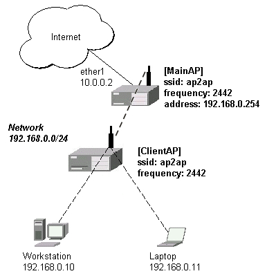
In our case the user is downloading at the maximum speed. This means he could download at the burst-limit speed 5min - average value is still equal to burst-threshold which is 200000 (400000*300/600=200000). In the next second the speed limit will be greater than the burst-threshold and the speed limit will be dropped to the max-limit. Using PCQSuppose we have a network and we want to limit Peer-to-Peer traffic for each client in this network to 64Kbit/s upload and 128Kbit/s for download. This queue type is called PCQ. You can also use it in the previous examples instead of the default queue type. First of all, create a PCQ queues - one for upload (this should classify by src-address), and one for download (this should classify by dst-address): /queue type add name=up kind=pcq pcq-classifier=src-address pcq-rate=64000 /queue type add name=down kind=pcq pcq-classifier=dst-address pcq-rate=128000 Then we should 'catch' the P2P traffic using mangle rule: /ip firewall mangle add p2p=all-p2p action=passthrough mark-flow=p2p Now we can create queues: /queue tree add parent=public flow=p2p queue=up /queue tree add parent=local flow=p2p queue=down How to make a Wireless Bridge, using WDS?DescriptionLet us consider that we have a MainAP wireless Access Point which serves several wireless clients (from network 192.168.0.0/24) and is connected to ClientAP which also serves clients from the same network. This example illustrates how to use WDS between MainAP and ClientAP so that they also act as APs for wireless clients.
At first, let us setup the wireless interface for MainAP: /interface wireless set wlan1 ssid=ap2ap band=2.4GHz-B
frequency=2442 mode=ap-bridge wds-mode=static disabled=no
Now add a WDS interface and note that the wds-address is MAC address from remote AP (in this case ClientAP): /interface wireless wds add master-interface=wlan1
wds-address=00:02:6F:01:CE:31 disabled=no
Put the wds1 and wlan1 interfaces into a bridge: /interface bridge add disabled=no /interface bridge port set 1,2 bridge=bridge1 [admin@MikroTik] interface bridge port> print # INTERFACE BRIDGE PRIORITY PATH-COST 0 ether1 none 128 10 1 wlan1 none 128 10 2 wds1 none 128 10 [admin@MikroTik] interface bridge port> Finally, add an IP address to the bridge1 interface: /ip address add address=192.168.0.254/24 interface=bridge1 [admin@MikroTik] ip address> print Flags: X - disabled, I - invalid, D - dynamic # ADDRESS NETWORK BROADCAST INTERFACE 0 10.0.0.2/24 10.0.0.0 10.0.0.255 ether1 1 192.168.0.254/24 192.168.0.0 192.168.0.255 bridge1 [admin@MikroTik] ip address> Now let us configure ClientAP. The configuration is similar to MainAP configuration. At first, configure the wlan1 interface: /interface wireless set wlan1 ssid=ap2ap frequency=2442
band=2.4GHz-B mode=ap-bridge wds-mode=static disabled=no
Then add a WDS interface: /interface wireless wds add master-interface=wlan1
wds-address=00:0B:6B:31:01:6A disabled=no
Add the wds1 and wlan1 interfaces to a bridge: /interface bridge add disabled=no /interface bridge port set wlan1,wds1 bridge=bridge1 If you want, you can assign an IP address to the bridge interface, but there is no need for it (as this AP works transparently). Now you are able to ping the clients from MainAP: /ping 192.168.0.10 192.168.0.10 64 byte ping: ttl=64 time=8 ms 192.168.0.10 64 byte ping: ttl=64 time=7 ms 192.168.0.10 64 byte ping: ttl=64 time=7 ms 3 packets transmitted, 3 packets received, 0% packet loss round-trip min/avg/max = 7/7.3/8 ms How to limit p2p traffic, using masquerading and PCQExampleLet us consider a situation where the limited network is 192.168.0.0/24. We will limit the p2p download traffic to 256kbit/s and upload to 128kbit/s The 192.168.0.0/24 network has to be masquaraded in order to get public access (it will use the address 10.0.0.217). To do so, we will masquerade this network.
[admin@MikroTik] ip firewall src-nat> add src-address=192.168.0.0/24
... action=masquerade
[admin@MikroTik] ip firewall src-nat> print
Flags: X - disabled, I - invalid, D - dynamic
 0   src-address=192.168.0.0/24 action=masquerade
[admin@MikroTik] ip firewall src-nat>
Then we have to mark download and upload traffic. To do so with masqueraded traffic, let's add 2 mangle rules - the first one stands for marking the p2p connection with the mark p2p_con which is comming from the local network (192.168.0.0/24) , the second one will mark all packets whithin this connection with mark p2p_limit, which will be used for limiting the upload and download traffic. [admin@MikroTik] ip firewall mangle>
add src-address=192.168.0.0/24 p2p=all-p2p
... mark-connection=p2p_con action=passthrough
[admin@MikroTik] ip firewall mangle>
add connection=p2p_con action=accept mark-flow=p2p_limit
[admin@MikroTik] ip firewall mangle>
Next, we will make two PCQ types - one for download (pcq-download), and one for upload (pcq-upload). [admin@MikroTik] queue type> add kind=pcq name=pcq-download ... pcq-rate=256000 pcq-classifier=dst-address [admin@MikroTik] queue type> add kind=pcq name=pcq-upload ... pcq-rate=128000 pcq-classifier=src-address [admin@MikroTik] queue type> print 0 name="default" kind=pfifo bfifo-limit=15000 pfifo-limit=50 red-limit=60 red-min-threshold=10 red-max-threshold=50 red-burst=20 sfq-perturb=5 sfq-allot=1514 pcq-rate=0 pcq-limit=50 pcq-classifier 1 name="ethernet-default" kind=pfifo bfifo-limit=15000 pfifo-limit=50 red-limit=60 red-min-threshold=10 red-max-threshold=50 red-burst=20 sfq-perturb=5 sfq-allot=1514 pcq-rate=0 pcq-limit=50 pcq-classifier 2 name="wireless-default" kind=sfq bfifo-limit=15000 pfifo-limit=50 red-limit=60 red-min-threshold=10 red-max-threshold=50 red-burst=20 sfq-perturb=5 sfq-allot=1514 pcq-rate=0 pcq-limit=50 pcq-classifier 3 name="synchronous-default" kind=red bfifo-limit=15000 pfifo-limit=50 red-limit=60 red-min-threshold=10 red-max-threshold=50 red-burst=20 sfq-perturb=5 sfq-allot=1514 pcq-rate=0 pcq-limit=50 pcq-classifier 4 name="pcq-download" kind=pcq bfifo-limit=15000 pfifo-limit=50 red-limit=60 red-min-threshold=10 red-max-threshold=50 red-burst=20 sfq-perturb=5 sfq-allot=1514 pcq-rate=256000 pcq-limit=50 pcq-classifier=dst-address 5 name="pcq-upload" kind=pcq bfifo-limit=15000 pfifo-limit=50 red-limit=60 red-min-threshold=10 red-max-threshold=50 red-burst=20 sfq-perturb=5 sfq-allot=1514 pcq-rate=128000 pcq-limit=50 pcq-classifier=src-address [admin@MikroTik] queue type> And finally, add the queue rules. [admin@MikroTik] queue tree> add name=down parent=Local
... flow=p2p_limit queue=pcq-download
[admin@MikroTik] queue tree> add name=up parent=Public
... flow=p2p_limit queue=pcq-upload
[admin@MikroTik] queue tree> print
Flags: X - disabled, I - invalid, D - dynamic
0 name="down" parent=Local flow=p2p_limit limit-at=0
queue=pcq-download priority=8 max-limit=0 burst-limit=0
burst-threshold=0 burst-time=0
1 name="up" parent=Public flow=p2p_limit limit-at=0 queue=pcq-upload
priority=8 max-limit=0 burst-limit=0 burst-threshold=0 burst-time=0
[admin@MikroTik] queue tree>
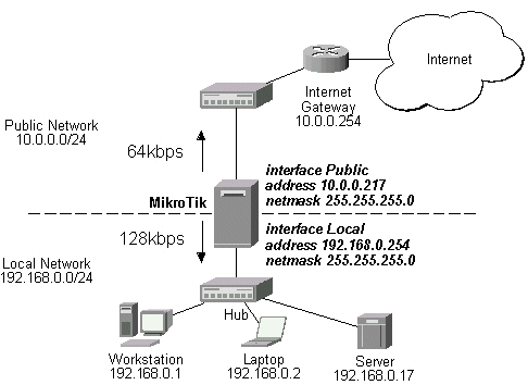
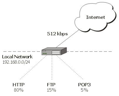
How to guarantee and prioritize traffic?DescriptionQueue trees can be used for more sophisticated applications where you need to limit traffic for specific users, protocols, ports etc. In this example we will show you:
You can see how we will share the traffic in the picture (the network 192.168.0.0/24 is masqueraded):
Note: for a correct queue tree setup the amount of limit-at values for queue tree leaves (queues which have no child-queues) must be equal (or lower) to available bandwidth. In this case 25,6kbps + 76,8kbps + 409,6kbps = 512kbps. |


 | Taśma stalowa stal nierdzewna (PL) C201, długość 50m, wymiary 20mm x 0,7mm |
| cena: 166,70zł |

 | Szafa wisząca 19" 6U, 350mm, drzwi szklane, szara (zestaw) |
| cena: 223,60zł | |
 | Tenda F6 |
| cena: 65,30zł | |
 | Zaciskarka złączy RJ-45/RJ-12/RJ-11/RJ-9 CT-N5684 |
| cena: 32,90zł | |
 | Tenda RX3 |
| cena: 216,20zł | |
 | Wisnetworks WIS-Q2300L Hi-Gain Wireless CPE |
| cena: 146,40zł | |

DHL: od 10.65 PLN (netto)
FedEx: od 14.90 PLN (netto)
Poczta: zgodnie z cennikiem
Zlokalizuj przesyłkę DHL
Zlokalizuj przesyłkę FedEx
Zlokalizuj Paczkę Pocztową